A Prediction of the Transient Phenomena by the Load Rejection for a 50MW Francis Hydropower Plant
Abstract
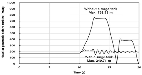
Generally, hydropower operates in a steady state when generating power. However, transient operations such as start-up and shut-down operations can trigger unsteadiness, which may cause accidents in severe cases. Therefore, hydropower plants include a protection device, such as a surge tank, and verifies the opening time of the guide vane at the design stage. To replace parts, such as runners for increasing the performance of the hydropower plant, sufficient verification is required. This study involves various transient operations in a Francis hydropower plant modeled using the 1-D Analysis (SIMSEN) software, which was developed for the simulations of hydraulic systems. During the simulations, the safety at power plants was examined by assessing the changes in the water level of a surge tank. Via simulations, it was verified that it operates stably even when an emergency shutdown occurs while the reservoir level is increased to the maximum. In addition, the surge tank reduced the maximum value of the head at the penstock before the turbine by 31.6% compared to that without a surge tank.
Keywords:
Hydropower plant, Renewable energy, Transient phenomena, Francis turbine, Surge tank키워드:
수력발전소, 신재생에너지, 과도 현상, 프란시스 수차, 서지탱크1. Introduction
Global warming is an important issue, and it is related to the growing interest in hydropower. Hydropower is currently a mature and cost-competitive renewable energy source(1). As an essential energy, it accounts for 15.9 % of the global electricity generation, with a supply of more than 4200 TWh annually(2-3), which helps to stabilize fluctuations between demand and supply. The role of hydropower will become even more important in the coming decades, because the shares of various renewable energy sources will increase considerably. Wind and solar power have the disadvantage of determining the amount and timing of generation depending on natural factors such as wind or sunlight, whereas hydroelectric power can determine the amount and timing of generation.
However, because hydropower plants adopt the peak-load generation method, which involves repeated starts and stops, it is inevitable to alter operating conditions and numerous transient processes. Specifically, sudden changes in guide vane openings can change the flow inertia, triggering changes in hydraulic pressure inside the penstock and the rotational speed of the turbine(4). These sudden changes cause what is termed a water hammer, and, in serious cases, cause accidents in hydropower plants. Therefore, methods for preventing transient phenomena should be verified via experiments and numerical analyses.
Kim et al.(5) adopted an inverse transient method with a genetic algorithm to identify leak information in a pipe. A systematic approach is necessary because the main components, such as the turbine, generator, penstock, surge tank, and valves, are connected to each other.
Tests or analytical approaches have been utilized as experimental methods or as assessments of single components, to analyze the water hammer phenomenon due to the closing of the valves or guide vanes of the turbine. For example, a test performed by Maryono et al.(6) reduced the water hammer phenomenon by increasing the valve closing time or via the installation of a bifurcation pipe at the front of the turbine.
The development of computer software has inspired studies on the overall stability of systems. In the study conducted by Liu et al.(7), a simulation demonstrated that the runaway speed of a Kaplan model turbine with ns = 479 m-kW is 1.45 times greater than the initial speed under rated conditions. Simulation studies on various transient situations are also being conducted, such as emergency shutdowns and overload surge phenomena present in hydropower plant systems(8-10). The development of software made it possible to analyze systems for unsteady states with time alterations at hydropower plants.
Existing studies have only been verified via simulations at the stage of designing a new hydro power plant. This study attempted to verify the stability in transient phenomena based on a 1-D simulation and model test in the case of changing the turbine runner to a novel design for an existing hydropower.
First, the effectiveness of the simulation was verified by comparing the data obtained from the field test with the simulation modeling results based on the existing runner. Accordingly, it was ascertained that the simulation was sufficiently reliable, as the similarity was confirmed. Subsequently, additional simulations were performed using the parameters obtained from the model test results of the new runner. The pressure increase inside the penstock was simulated according to the dam level condition, the presence or absence of a surge tank, and the opening time of the guide vane.
2. Modeling of a Francis hydropower plant
2.1 Field test and model calibration
The hydropower is overhauled at regular intervals to check and maintain the stability of the equipment. At this point, the load rejection, force for guide vane opening and closing, and output test are performed, to evaluate the hydro turbine and generator. Among these tests, the load rejection ensures that the hydro turbine generator safely switches to a no-load or shutdown state when a power system or mechanical accident occurs during normal operation.
The accuracy of the simulation was verified by comparing the results of the field test and simulation analysis for the load rejection of the 50-MW Francis turbine. Table 1 presents the conditions and specifications of the modeled operating hydropower system and Francis turbine, respectively.
In the load rejection test, the stability of the turbine generator is verified by measuring the inlet pressure head, rotation speed, and voltage of the generator.
Table 2 presents the measurement items and equipment, while the installation location is illustrated in Fig. 1.
The generator circuit breaker system was opened manually for the test; accordingly, the measured data before and after the load rejection are presented in Table 3.
To verify the reliability of the simulation, modelling was performed under conditions identical to those adopted in the field test. Among the major components of the dam, the waterway has a total length of 2634.61 m from the reservoir to the surge tank, and the penstock is 218.61 m from the surge tank to the Francis turbine. The model comprises two Francis turbines branching at 132.11 m at the penstock.
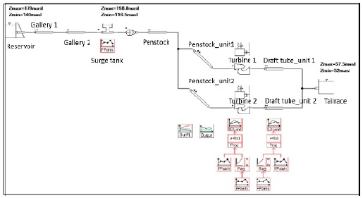
The field test conditions are as follows. The rejection load, rotational speed, inlet pressure head, and guide vane servomotor stroke were 50.2 MW, 257 rpm, 101.7 mAq, and 225.7 mm, respectively. At this point, the reservoir and tailrace levels were 159.25 m and 56.2 m, respectively. To determine the initial condition of a hydraulic system with the Francis turbine, stabilization is conducted using these parameters. The specified rotational speed (Nc) and turbine torque (Tc) are known, while the corresponding guide vane opening (yc) is determined. Consequently, the specified operating points were determined to be Nc = 257 rpm, Tc =1.903106, and yc=0.8102. Table 4 presents the simulation conditions including boundary conditions such as the reservoir level. Fig. 2 presents the simulation modeling diagram.
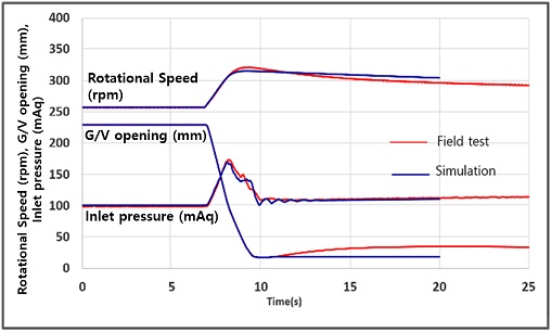
Fig. 3 presents a comparison of the simulation results with the field tests under identical conditions. In the field test, the inlet pressure head of the surge tank increased from 101.7 mAq at the beginning of the test to a maximum value 173.6 mAq after load rejection. In the simulation, the inlet pressure increased from 100.71 mAq at the beginning of the simulation to a maximum value of 169.09 mAq after load rejection. The difference in the maximum inlet pressure between the simulation and the field tests was 2.6 %. The rotational speed of the turbine increased to 321.4 rpm in the field test, while that of the simulation increased to 315.06 rpm, resulting in a 1.97 % difference between the simulations and field tests. The simulated results under conditions identical to those in the field test results for a load rejection exhibit a certain degree of similarity.
2.2 Numerical methods
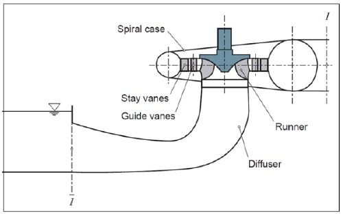
Hydropower plants consist of several components that must be included when modelling their dynamic behaviors. The Francis turbine has fixed runner blades; hence, the discharge through the turbine is controlled by the guide vane. Fig. 4 presents a simplified cross-sectional view of a vertical Francis turbine as a plant to be analyzed. From the right, the water passing through the penstock passes through the spiral case, rotates the runner, and is discharged through the diffuser(11).
Under an unsteady flow, the conditions at a point change with time and the velocity varies along the pipe. The terms “water hammer” and “transient flow” are used synonymously to describe the unsteady flow of a fluid in a pipeline(12). The momentum and continuity equation are basic differential equations for transient flow.
The momentum equation expresses the balance of the forces acting on the fluid volume, the momentum flux through the surfaces, and the rate of change of the momentum in the volume itself. The integral form of the momentum equation applied to a volume of fluid is expressed in Equation (1), while the mass balance in a control volume is expressed in Equation (2).
| (1) |
| (2) |
where, ρ, , , , and dA denote the density of water [kg/m3], flow velocity [m/s], norminal vector, moving velocity of the control volume [m/s], and cross-sectional area [m2], respectively.
From these equations, we can calculate an unsteady flow via several methods, such as characteristics, algebraic, and implicit method. In this study, we employ the 1-D hydraulic analysis software (SIMSEN)(13) developed by the EPFL Laboratory for transient phenomena in hydraulic systems.
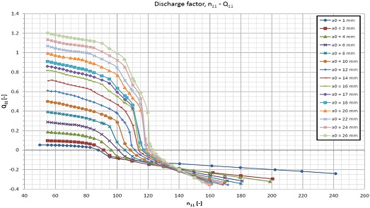
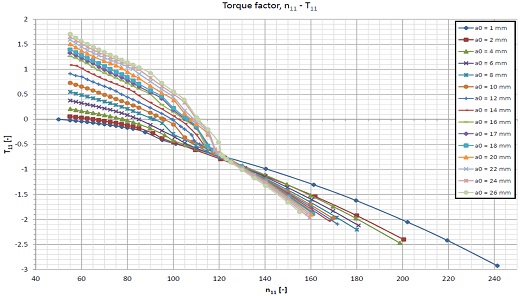
The main hydropower turbine characteristics can be expressed by performance-characteristic curves or in a model efficiency hill chart based on the water head and flow rate coordinates or unit parameter coordinates(14). In this study, Francis turbine-characteristics derived based on a model test using a turbine runner with a novel shape were applied as dimensionless terms n11, Q11, and T11, which were converted to values per unit dimension and per unit head(15). The rotational speed, discharge factor, and shaft torque factor are expressed in Equations (3), (4), and (5), respectively.
| (3) |
| (4) |
| (5) |
where, n, Dref, Q, H, and Tm denote the rotational speed [rpm], turbine reference diameter [m], discharge [m3/s], turbine head [m], and model turbine shaft torque [N⋅m], respectively.
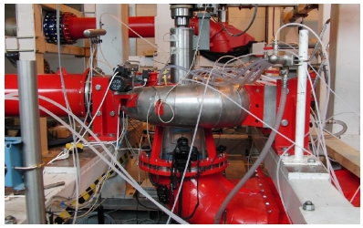
Figs. 5 and 6 show the correlation between n11, Q11, and T11 for various guide vane openings during the Francis turbine model testing. As the rotational speed factor increases, the discharge factor has a negative value, which means the reverse flow that may occur in transient phenomena. At the same time, the shaft torque factor also has a negative value, which means operation as a pump rather than a turbine. Fig. 7 and Table 5 detail the model tests performed in accordance with IEC-60193 to derive these graphs.
3. Results and discussion
3.1 Simulation of the surge tank level
A hydropower plant shutdown of the water flow involves closing the turbine guide vane rapidly in the event of an emergency situation. When the pressure in the penstock increases to an extreme level outside of the allowable value, accidents may occur such as the rupture of the penstock, buckling due to negative pressure, damage to turbines, and inability to open and close inlet valves(16). To absorb pulsation, which may occur in the penstock owing to the sudden change in the flow rate, hydropower plants are equipped with protection systems, such as a surge tank. The surge tank’s height should be properly designed to ensure stability against transient phenomena occurring in hydropower plants. In this study, the surge tank level under two reservoir level conditions was analyzed, assuming an emergency shutdown situation after the loading of the hydropower plant. At this point, the changes in the surge tank level according to the reservoir level were analyzed. The total simulation time was 20 s, and each integration step was 0.005 s.
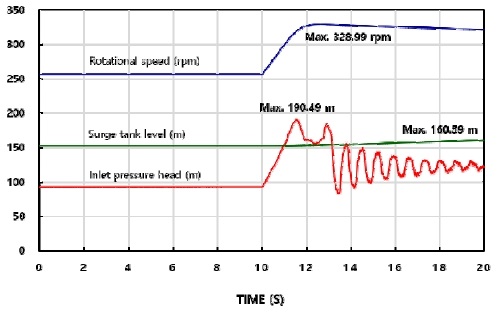
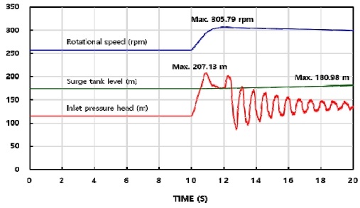
We simulated the changing of reservoir levels. Fig. 8 and 9 present the analysis results at the dam water level under two conditions. The first is an average operating water level of 160 m, based on data accumulated over the past 27 years. Second, because the water level of the dam and the pressure of the penstock and surge tank are in a proportional relationship, it was set to 179 m, which is the operational maximum water level at which the maximum pressure will emerge. The water level in tailrace was set to 57.5 m in both conditions.
Oscillation occurs at the inlet pressure as soon as the emergency shutdown starts. respectively, while the emergency shutdown occurs 10 s after loading. The surge tank level increases to 160.59 m when the reservoir level is 160 m. When the worst condition occurs, i.e., when the reservoir level is 179 m, the surge tank level increases to 180.98 m. Table 6 presents the rate of increase after the start of the emergency shutdown compared to the initial conditions.
The maximum level of the modelled dam’s surge tank was 198.8 m, which verified that the stability of the hydropower plant is ensured even when an emergency shutdown situation occurs while the reservoir level is maximized.
The following is a comparison of the oscillation generated by the penstock before the Francis turbine with and without a surge tank in a hydropower plant. The simulation conditions are as follows: the reservoir and tailrace levels are 179 m and 57.5 m. Fig. 10 presents the change in the pressure head at the penstock at the inlet turbine, with or without a surge tank. Without a surge tank, the pressure head increased sharply, reaching a maximum of 762.58 mAq. However, the pressure head increased to only 240.71 mAq with a surge tank.
3.2 Simulation changing the guide vane close time
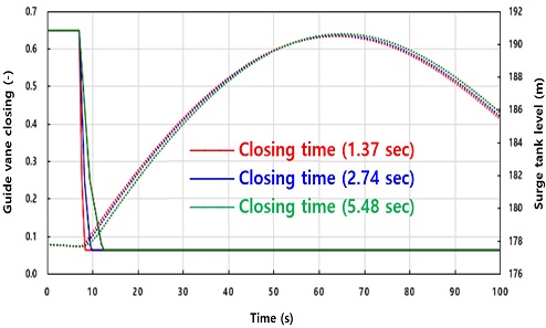
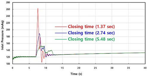
We decided to change the closing time of the guide vane to observe the effects on the pressure rise triggered by a transient in a hydropower plant. This simple method can influence how the increased pressure due to a transient changes the guide vane closing time. The present guide-vane closing time was 2.74 s. We shortened this closing time to 1.37 s and extended it to 5.48 s, and then conducted the simulations under identical conditions.
Fig. 11 presents a graph of the guide vane closing times and indicates that even with changes in the guide vane closing times, the level of the surge tank does not vary significantly. However, Fig. 12 demonstrates that the pressure at the immediate inlet of the turbine varies considerably. If the current guide-vane closing time is approximately doubled, the maximum pressure can be reduced by approximately 19%, from 189.05 mAq to 152.32 mAq. In contrast, if the guide vane closing time can be shortened by one half, the maximum pressure will increase abruptly from 189.05 mAq to 262.93 mAq. Therefore, we can confirm that adjusting the closing time of the guide vanes can be a viable means of mitigating the increased pressure caused by a transient at the hydropower plant.
4. Conclusions
In this study, before applying the novel runner to the existing hydropower plant, it was verified to be sufficiently safe even in transient conditions. Simulations were conducted using a 1-D Analysis software of unstable operations, which in this case was an emergency shutdown of the type that can occur at a hydropower plant. Accordingly, the following conclusions were reached.
1) To verify the reliability of the simulation, the simulation model was compared with the data obtained from the plant where the existing runner was installed. The difference was 2.6% for the maximum inlet pressure and 1.97% for the maximum rotational speed.
2) Simulation was performed using the parameters derived from the model test using the novel runner. Although an emergency stop occurred at the maximum water level of the dam at 179 m, it was safe, as it was lower than the maximum water level of the 198.8 m surge tank. The surge tank reduced the maximum value of the head at the penstock before the turbine by 31.6% compared to that without a surge tank; however, if the guide vane closing time can be shortened by one half, the maximum pressure will rise abruptly from 189.05m to 262.93m.
3) In conclusion, even when the runner was changed to a novel design, it was confirmed to be stable in transient phenomena.
Acknowledgments
This research was conducted with the Korea Agency for Infrastructure Technology Advancement (KAIA) under the Ministry of Land, Infrastructure, and Transport (No. 21IFIP-B128598-05) and the Korea Institute of Energy Technology Evaluation and Planning (KETEP) under the Ministry of Trade, Industry & Energy, Republic of Korea (No. 201530 10060310).
References
- International Energy Agency, 2012, Technology Roadmap Hydropower.
- International hydropower association, 2019 hydropower status report, 2019.
- International Hydropower Association, 2016 Key trends in hydropower, 2016.
-
Liu, Y., Yang, J., Yang, J., Wang, C., Zeng, W., 2016, “Transient Simulations in Hydropower Stations Based on a Novel Turbine Boundary,” Mathematical Problems in Engineering, Vol. 2016, pp. 1-13.
[https://doi.org/10.1155/2016/1504659]

-
Kim, Y. J., Miyazaki, K., Tsukamoto, H, 2008, “Leak detection in pipe using transient flow and genetic algorithm,” Journal of Mechanical Science and Technology, Vol. 22, pp. 1930-1936.
[https://doi.org/10.1007/s12206-008-0735-8]

- Maryono, A., Suhanan, Kurniawas, A., Alatas, M., Akhita, A. M. R., Wicaksono, A. B., 2013, “Experimental study of Water Hammer Phenomena in Drinking Water Pipeline Distribution Using Video Camera Method,” International Journal of Scientific & Engineering Research, Vol. 4, pp. 1-8.
-
Liu, S., Zhou, D., Liu, D., Wu, Y., Nishi, M., 2010, “Runaway transient simulation of a model Kaplan turbine,” 25th IAHR Symposium on Hydraulic Machinery and Systems, Vol. 12, pp. 1-8.
[https://doi.org/10.1088/1755-1315/12/1/012073]

- Ruchonnet, N., Nicolet, C., Avellan, F., 2006, “Hydroacoustic Modeling of Rotor Stator Interaction in Francis Pump-Turbine,” IAHR Int. Meeting of WG on Cavitaion and Dynamic Problems in Hydraulic Machinery and Systems, pp. 1-28.
-
Nicolet, C., Alligne, S., Kawkabani, B., Simond, J.-J., Avellan, F., 2009, “Unstable Operation of Francis Pump-Turbine at Runaway: Rigid and Elastic Water Column Oscillation Modes,” International Journal of Fluid Machinery and System, Vol. 2, No. 4, pp. 324-333.
[https://doi.org/10.5293/IJFMS.2009.2.4.324]

- Nicolet, C., Alligne, S., Kawkabani, B., Koutnik, J., Simond, J.-J., Avellan, F., 2009, “Stability Study of Francis Pump-Turbine at Runaway,” 3rd IAHR International Meeting of the WorkGroup on Cavitation and Dynamic Problems in Hydraulic Machinery and Systems, pp. 371-384.
- Nicolet, C., Hydroacoustic Modeling and Numerical Simulation of Unsteady Operation of Hydroelectric Systems, Ph.D. thesis, No. 3751, Federal Institute of Technology Lausanne(EPFL), Switzerland.
- Wylie, E. B., Streeter, V. L., 1993, Fluid Transients in Systems, New Jersey: Prentice-Hall.
- Nicolet, C., Allenbach, P., 2002, “New Tool for the Simulation of Transient Phenomena in Francis Turbine Power Plants,” Hydraulic Machinery and Systems 21st IAHR Symposium, pp. 1-8.
-
Guo, P., Wang, Z., Sun, L., Luo, X., 2017, “Characteristic analysis of the efficiency hill chart of Francis turbine for different water heads,” Advances in Mechanical Engineering, Vol. 9(2), pp. 1-8.
[https://doi.org/10.1177/1687814017690071]

- KS B 6018:2015, Methods for Modeltests of Hydraulic Turbine and Reversible Pump-turbine.
-
Lee, Y. B., Kim, K. Y.. 2019, “A Study on Hydraulic Transient Phenomenon of a Pumped Storage Power Plant (Ⅰ),” The KSFM Journal of Fluid Machinery, Vol. 22, pp. 35-43.
[https://doi.org/10.5293/kfma.2019.22.5.035]


