Design and Performance of a Pico Propeller Hydro Turbine Model
Abstract
Water supply networks (WSN) are important structures in urban and industrial environments that are built to transport fluid between several supply and demand points. However, a significant amount of pressure energy still remains at the end of the water supply pipe system. This energy is usually released and wasted. Therefore, a pico propeller turbine was chosen as a solution to recover the energy. In order to study more deeply on the performance of a pico propeller turbine in a laboratory environment, a new runner model was designed to improve the performance of the existing runner model. The design of the new runner blade model considers several key parameters such as the hub-tip diameter ratio and velocity triangle calculation which govern blade performance. The performance of the new runner model was evaluated by CFD analysis and compared with the performance characteristics of the old runner model. The internal flow and cavitation performance were also investigated for the new runner design.
Keywords:
Pico Propeller Hydro Turbine Model, Runner Design, Performance Characteristics, Loss Analysis, Cavitation Performance키워드:
피코 프로펠러 수차 모델, 러너 설계, 성능 특성, 손실 분석, 캐비테이션 성능1. Introduction
Water supply networks (WSN) are important structures in urban and industrial environments that are built to transport fluid between several supply and demand points. However, a significant amount of pressure energy still remains at the end of the water supply pipe system. This energy is usually released and wasted. Many researchers have studied methods to recover the remaining energy in the WSN by using small scale hydropower [1-3]. Small scale hydropower can be classified into small, mini and micro or pico hydros depending on the output power and the type of the adopted scheme [4,5]. There are not yet globally accepted boundaries to define these classes. It usually depends on the country, but micro-hydro typically refers to schemes below 100kW [6] while pico hydro usually corresponds to the installed power of less than 5kW [7]. Equation (1) is the general formula for the output power of any hydropower system output:
| (1) |
Where P , Q and H are the output power produced at the turbine shaft (watts), flow rate passing through the turbine (m3/s) and effective pressure head of water across the turbine (m), respectively. η is the hydraulic efficiency of the turbine. ρ is the density of working fluid (kg/m3). g is the acceleration due to gravity (m/s2). Micro-hydropower generation efficiency is generally in the ranges of 60%-80% [4]. P. Singh et al. [8] carried out experimental optimization of a propeller turbine working with low head from 1.5-2 m and geometrical changes at the inlet tip and outlet tip blade angles of the runner. R. Simpson et al. [9] designed and implemented a 5kW class propeller turbine with the head ranges of 3-4 m and reported a maximum efficiency of 65%. K. Alexander et al. [10] attempted to standardize four propeller turbine models working with the head ranges of 3-9m and generated power in the ranges of 1.5-3 kW and has recorded peak efficiency in the ranges of 68-74%. The maximum efficiency of 74% has been recorded by experiment.
The aim of this study is to design a new runner model of a pico class propeller turbine for improving the performance of the old runner model. Also, the newly designed runner model will be evaluated by CFD analysis and compared with the performance characteristics of the old runner model.
2. Performance test facility of turbine model
2.1 Propeller turbine model test facility
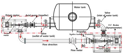
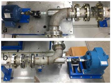
The schematic of the propeller turbine model test facility is introduced in Fig. 1. Fig. 2 shows the axial pump model and propeller turbine model in detail. The propeller turbine model was horizontally installed in the test system which consists of an axial flow pump driven by a motor, two gate valves, a flow meter, a propeller turbine, a dynamometer and a water tank. The inner diameter of the pipe system is 155 mm but the casing inner diameters of the axial pump model and the propeller turbine model are both 151 mm with 0.5 mm tip clearance between the blade tip and the casing inner wall. As the tip gap less than 0.15 mm is not recommended [11], for manufacturing easier, the 0.5 mm tip gap was chosen. Pressure transducers are installed at the inlet and outlet pipes of the axial pump and the propeller turbine models to measure the pump and turbine heads, respectively. Dynamic torque meters are installed to measure the shaft speed and output torque. All measurement signals for each operating condition are recorded to a data logging system.
2.2 The old propeller turbine model performance
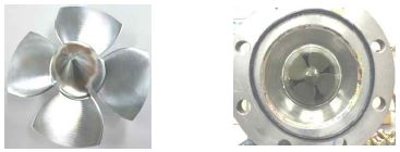
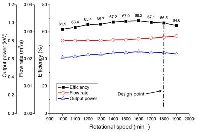
The old runner model which has a runner diameter of 150 mm was manufactured and installed within an inline pipe as shown in Fig. 3. In the experimental apparatus, the old runner model has no guide vane for the simplification of the pico propeller turbine model system. The experimental results of the old runner model are shown in Fig. 4. The efficiency of the old runner model at the design point is 66.5% which is a general value [4] but quite low yet for the commercialization of the pico propeller turbine. Therefore, a new propeller turbine needs to be designed to improve the performance.
3. Design of new propeller turbine model
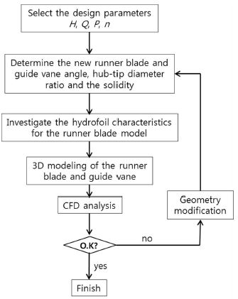
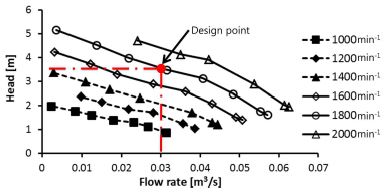
Fig. 5 illustrates the flow chart of a design process for the new propeller turbine model. Input power of the turbine runner is fed by the axial flow pump as shown in Fig. 1. Therefore, the design point of the new runner model is determined by the existing pump performance and pipe loss between the axial pump and the turbine model. The pump performance is shown in Fig. 6. The design parameters of the new propeller turbine model are shown in Table 1.
3.1 Determination of the runner blade angle
Dixon [12] concluded that the free vortex method can be applied to the incompressible flow for Kaplan turbines as well as the compressible flow for gas turbine and compressors. K. Alexander [10] and P. Sing [8], used the free vortex method for their propeller turbine runner design. Therefore, the free vortex method has been applied to the flow from the guide vane outlet to the runner blade inlet in this study. The guide vane outlet angle and runner blade inlet angle have been calculated by the free vortex method with the assumption that there is no energy loss. The form of the free vortex principle comes from the conservation of angular momentum. This is illustrated by equation (2)
| (2) |
This is the starting point for calculating the runner blade inlet angle with the known constant k. The value of constant k can be found in equation (3) which is called the Euler’s head equation. Where Hth , Vu and u are the theoretical head, tangential velocity and peripheral velocity, respectively. Indicators 1 and 2 refer to the inlet and outlet of the runner blade, respectively. In order to achieve maximum energy transfer from the runner blade, the flow at the outlet of the runner blade should have no swirl flow. This means that Vu2 = 0.
| (3) |
Combining the equations (2) and (3) while considering the condition of no swirl flow at the runner outlet, the constant k can be substituted to form equation (4).
| (4) |
3.2 Design of runner blade shape
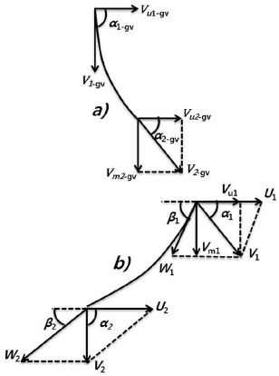
Fig. 7 represents the velocity diagrams of the runner blade and guide vane at a cylindrical section. In this study, from the hub to tip of the runner blade, five cylindrical sections are equally divided on the runner blade surface. In each section, the velocity triangle is calculated at the runner inlet and runner outlet points following the expressions:
At the runner inlet point:
where
At the runner outlet point:
where
Where β, Dh , D and Vm are the runner blade angle, hub diameter, runner diameter and meridional velocity, respectively. The blade angle varies at each cylindrical section due to the variation of the relative flow angle from the hub to the tip of the blade inlet. The hub-tip diameter ratio,Dh /D, defines the hub diameter and annulus flow area for a propeller turbine. According to P. Singh [8], the choice of the hub to tip ratio and number of blades technically depends on the specific speed of the turbine. However, a designer's freedom can also be exercised in choosing the values. Table 2 shows the Dh /D from previous studies and includes the hub-tip diameter ratio used in this study. A hydrofoil was used in four sections, and the modified hydrofoil shape is utilized in the hub section of the new runner model due to its structural safety enhancement of the new runner model. The shape and dynamic characteristics of the hydrofoil are shown in Fig. 8. The hydrofoil characteristics were investigated at varying Reynolds number and angle of attack by using a commercial code of ANSYS CFX [13]. The figure shows that the highest lift to drag ratio was achieved at an angle of attack of 10 degrees in both cases. Figs. 9 and 10 compare the runner blade shape and 3D modeling between the old and new runner models. Table 3 compares the geometrical parameters of 2 runner models. Both of the runner models have same the solidity factor but different number of blade. As a result, the chord length in the new runner is shorter than that of the old runner model.
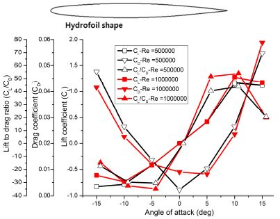
Dynamic characteristics of hydrofoil used for the new runner model at Reynolds number of 500000 and 1000000
3.3 Design of the guide vane
The design of old runner model did not include a guide vane. However, a guide vane was designed for the new runner model in order to improve the turbine performance, especially in efficiency more. The design method of the guide vane is similar to the design of the runner blade. To determine the guide vane angle, the free vortex method was applied to calculate the guide vane outlet according to the following expressions:
Where the character “gυ” represents the value at the guide vane. Like the runner blade model, the guide vane shape is also designed with a hydrofoil. The number of the guide vane is designed with 7 vanes.
4. Numerical method
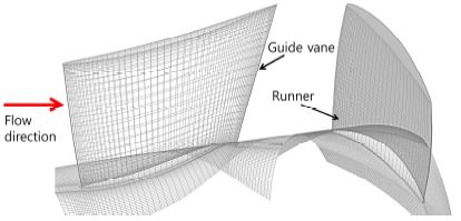
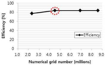
A commercial software of ANSYS CFX is used in this study. The mesh of one pitch of the new runner blade and guide vane model passages is shown in Fig. 11. The numerical grid for whole passage domain was constructed using a hexahedral grid. To decide the grid number in the propeller turbine, four high quality structured mesh sizes were investigated by CFD analysis.
Fig. 12 indicates the relationship between the grid number and the efficiency of the full passage domain of the propeller turbine. Since the turbine model efficiency does not change significantly over 4.5 million nodes, a mesh grid number of 4.5 million was selected for this study. An O-grid is used for the runner blade and the guide vane to increase the density of the grid layer number near the walls to achieve reasonable CFD analysis results. Moreover, the averaged y+ value of the runner blade is 11.3. The boundary conditions for CFD analysis on the turbine performance prediction are indicated in Table 4. The Rayleigh-Plesset model was used to predict the cavitation performance of the both runner models.
5. Results and discussion
5.1 Performance curves
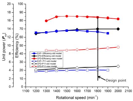
Fig. 13 compares the turbine performance curves by the old and new runner models. The experimental efficiency of the old model is almost agree well with the CFD analysis result below the range of rotational speed of 1600 min-1. The different efficiency of the old turbine between the experimental and CFD results may be due to mechanical loss increasing at high rotational speed (>1600 min-1) in the system. The figure clearly shows that the efficiency and power curves by the new runner model are higher than those by the old runner model. According to the CFD analysis results, the maximum efficiency by the new runner model is 84.0% which is approximately 14% higher than that by the old runner model at the design point. The experimental result of the new turbine model will be compared with that of the old turbine model in the future.
Moreover, unit power (P11 ), shown in equation (5) was used to compare the performance of the two runner models. The unit power produced by the new runner model largely higher than that by the old runner model at the design rotational speed.
| (5) |
5.2 Loss analysis
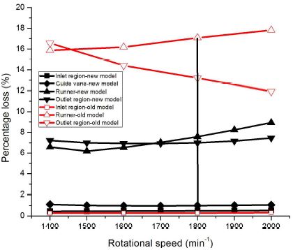
To investigate the component losses of the propeller turbine, four sub-domains were divided in the flow field namely; inlet region, guide vane region, runner region and outlet region. The first domain is the inlet region and is defined from the intake pipe inlet to the inlet of the guide vane. The second domain is the guide vane region which is defined from the inlet of the guide vane to the runner inlet. The third domain is the runner region which is defined from the runner inlet to the inlet of the discharge pipe. The final domain is the outlet region from the inlet of the discharge pipe. Equations (6) and (7) are applied for the results of CFD analysis to calculate the losses at the inlet, guide vane, outlet and runner regions, respectively.
| (6) |
| (7) |
Where Δp is the total pressure difference in the analysis region. H is the total head and Q is the flow rate supply at the inlet of the propeller turbine. The character “RN ” represents the value at the runner region. Fig. 14 shows local losses distribution by the turbines at varying rotational speed. In the old model, when increasing the runner rotational speed, the swirl intensity decreases in the outlet region. It relates to reduction of the loss at the outlet region. However, the loss in the runner region of old model increased. The losses in the runner and outlet regions are significantly reduced by the new runner model in comparison with those by the old runner model. This may explain why the efficiency of the new model improves by 14% at the design point. The losses at the inlet and guide vane regions of the new model show almost no changes at different rotational speeds. The runner region’s loss gradually increases as the rotational speed increases in both runner models. The loss at the outlet region of the new turbine model shows the lowest value at the design point.
5.3 Pressure coefficient and streamline distribution on the blade surface
The pressure coefficient (Cp ) is calculated by the following equation (8) using the CFD analysis results.
| (8) |
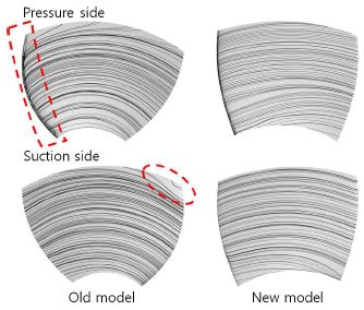
Where p and are the local static pressure and averaged reference static pressure on the blade surface. Fig. 15 shows the one blade pressure coefficient at the local span positions of the runner blade models. The output torque is generated by the pressure difference between the pressure and suction sides of the runner model. In the new runner blade model, the pressure difference between the pressure and suction sides is larger than that of the old runner model. As a result, there is significant increase in the unit power produced by all blades of the new runner model as seen in Fig. 13. Fig. 16 indicates comparison of streamline distribution on the old and new runner blade surfaces at the design rotational speed. The numerical result represents that the position of the stagnation line on the runner blade surface moves toward the pressure side for old runner model. In contrast, uniform streamline distribution along the new runner blade surfaces is found at the design point. It results in the better efficiency is achieved in the new turbine model in comparing with the old turbine model. Consequently, the efficiency of the runner model was relatively high with the uniform flow. However, near the tip (span 0.9) of the new runner model, the suction side pressure coefficient near the leading edge is relatively quite small which could result in cavitation near the tip area.
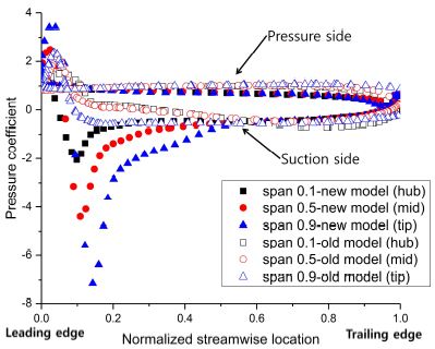
Comparison of pressure coefficient on the old and new blade model surfaces at the design point (1800 min-1)
5.4 Cavitation performance
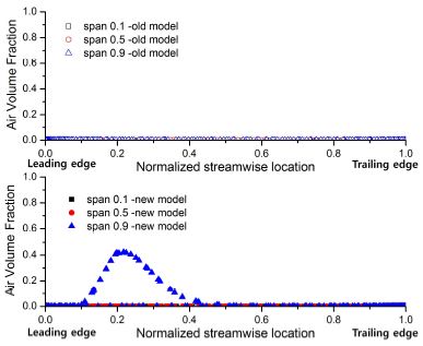
In order to predict the cavitation performance on the runner blade surfaces, the value of air volume fraction (AVF) was examined on the two runner blade models at the design point (1800 min-1). The range of AVF is from 0 to 1; where a value of “1” means that air bubbles are completely formed, resulting in high cavitation occurrence. Fig. 17 shows that the AVF values of the old runner blade model are almost “0” at the all local span positions on the runner blade surface; this means that the possibility of cavitation occurrence in the old runner blade model is very low. However, the maximum value of AVF of the new runner model is 0.43, which is much higher than that of the old runner model because the pressure coefficient distribution at the leading edge on suction side of the new runner blade model is lower than that of the old model as shown in Fig. 15. Nevertheless, the AVF value of the new runner blade model is quite below the limit of cavitation occurrence.
6. Conclusions
In this study, the new runner and guide vane models of the pico propeller turbine were designed to improve the performance of the existing old runner model. By comparison of the CFD analysis results for the old and new turbine models, it can be identified that the new model achieves an efficiency of 84.0% which is 14% higher than that of the old model. The efficiency improvement in the new turbine model is almost due to the significant loss decrease in the runner and outlet pipe regions. It means that the new turbine model is designed better than the old turbine model. The unit power by the new runner model has improved considerably higher than that by the old runner model. Moreover, the cavitation performance of the new runner blade model showed an acceptable range of the air volume fraction, which is quite below the limit of cavitation occurrence.
Acknowledgments
This work was supported by the New and Renewable Energy of the Korea Institute of Energy Technology Evaluation and Planning (KETEP) grant funded by the Korea Government Ministry of Trade, Industry and Energy (No. 20163010060340).
References
-
A. Carravetta, G. Giuseppe, O. Fecarotta, and H. M. Ramos, (2013), “PAT Design Strategy for Energy Recovery in Water Distribution Networks by Electrical Regulation”, Energies, Vol. 6, p411-424.
[https://doi.org/10.3390/en6010411]

- A. McNabola, et al., (2014), “Energy Recovery in the Water Industry using Micro-hydropower: an Opportunity to Improve Substantiality”, Water Policy, Vol. 16, p168-183.
-
H. M. Ramos, M. Mello, and P. De, (2010), “Clean Power in Water Supply Systems as a Sustainable Solution: from Planning to Practical Implementation”, Water Science and Technology: Water Supply, Vol. 10(No. 1), p39-49.
[https://doi.org/10.2166/ws.2010.720]

-
O. Paish, (2002), “Small Hydro Power: Technology and Current Status”, Renewable and Sustainable Energy Reviews, Vol. 6(No. 6), p537-556.
[https://doi.org/10.1016/s1364-0321(02)00006-0]

- H. Ramos, (2000), “Guidelines for Design of Small Hydropower Plants”, WREAN (Western Regional Energy Agency and Network) and DED (Department of Economic Development).
- H. Ramos, and A. Borga, (2009), “New design for Low-power Energy Production in Water Pipe Systems”, Water Science and Engineering, Vol. 2(No. 4), p69-84.
- M. Arriaga, (2009), “Pump as Turbine-A pico-hydro Alternative in Lao People’s Democratic Republic”, Renewable Energy, Vol. 35, p1109-1115.
-
P. Singh, and F. Nestmann, (2009), “Experimental Optimization of a Free Vortex Propeller Runner for Micro Hydro Application”, Experimental Thermal and Fluid Science, Vol. 33(No. 6), p991-1002.
[https://doi.org/10.1016/j.expthermflusci.2009.04.007]

- R. Simpson, and A. Williams, (2011), “Design of Propeller Turbines for Pico Hydro”, Retrieved June 15, 2012, from www.picohydro.org.uk.
-
K. V. Alexander, E. P. Giddens, and A. M. Fuller, (2009), “Axial-flow Turbines for Low Head Microhydro Systems”, Renewable energy, Vol. 34, p35-47.
[https://doi.org/10.1016/j.renene.2008.03.017]

- International Standard IEC 60193, (1999), 2nd Edition.
- S. L. Dixon, (2004), “Fluid Mechanics Thermodynamics of Turbo Machinery-5th Edition”, Elsevier B. Heinemann.
- ANSYS Ins, (2017), “ANSYS CFX Documentation”, Ver. 18.1, http://www.ansys.com (2017).
